1. I will make the beginning of the railway vehicle.
The deal on the first preparation of the railway vehicle, it is the first part than anything. First part is the face of railway vehicles, maintenance of post and make cool is here also go smoothly.
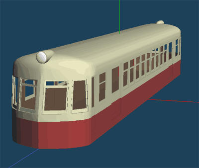
I will continue to make the body of a railway vehicle that descended took the world by storm in the early Showa era (in Japan) of "streamlined movement" this time.
(1) I want to create a standard of nose shape
The combination in the rough box-top shape first, grasp a rough measure of shape.
Create by adjusting the distance of the XYZ direction by selecting the rectangular solid from [Primitive] boxes. (Figure 1)
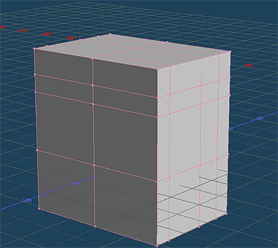 |
| Figure 1.Creating a train head part standard box |
It is just a box at this point, but I'll put in the [Knife] the necessary dividing line for configuring the nose shape.
(2) Edit the first reference shape
Delete based on the reference box at the top shape for creating that you created above, select the surface to be removed in the [Select]. (Figure 2)
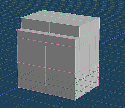 |
| Figure 2. Edit the train head part standard box |
In this way, remove the polygon part of cutting the shape, we will put the necessary Face using the [Create] if necessary.
It also creates a single-sided one, and automatically generates the other half using a mirroring function when creating a symmetrical shape as railway vehicle. Select the one side polygon shape data of the above in order to respond to this mirroring, and then delete them. (Figure 3)
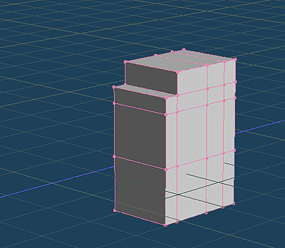 |
| Figure 3. Edit the train head part standard box-shaped (half of) |
(3) I fix the head part reference shape
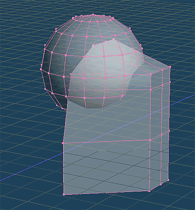
I am close to the sleek stretch from here to the head part reference shape the train was a box-until now. To do so, it cut the standard box-shape, we will create a reference shape due to the oblique.
Specifically, select individually in the [Select] unnecessary faces, and we will continue to set the required in the [Create]. There is a need to ensure that you do not remove the necessary points together polygons with at this time, when you work with carefully selected the order of the removal of . (Figure 4)
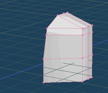 |
| Figure 4. Remove the unwanted from the train head portion standard box type and to create a streamlined reference shape |
Nose shape the train has been seen vaguely to come up here. But the train does not have the shape of angular so. Next we will create a train head portion a specific shape rounded shapes angular.
(4) I set the curved surfaces at the head shape
In order to apply a quick curved surfaces at the head shape, I will use the [Primitive] also this. It is to apply a portion of the sphere to the part where you want to set the curved surfaces.
Select the sphere in the [Primitive] Specifically, place to set the center of the sphere to the center point of the first part of the center line-shaped roof. The number of prints that can and 16, V direction 8 U direction. Selected work after you generate will be a little easier to be in a different sphere object in this case. (Figure 5)
 |
| Figure 5. I want to put the ball at the beginning reference shape |
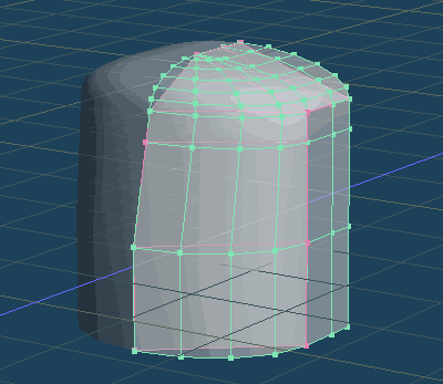
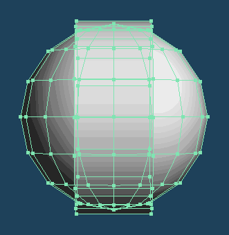
Select it in the the [Select] polygons of the sphere, and then remove, leaving a 1/8 an edge portion before. Change the scale each in XYZ axis direction by selecting [Scale] spheres the remaining portions then, you can fix the form curved surfaces so that the expansion in the form along the roof. (Figure 6)
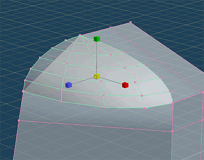 |
| Figure 6. The scale to deform the spherical along the top reference shape |
It is shaped like the shape of the lower front also be cylindrical in shape along the shape of the roof further. As with the previous method, which is also to place the shape by selecting the [Primitive], but choose a cylindrical type now. You have a 16 U direction the number of divisions, but the V direction is OK remain 1. (Figure 7)
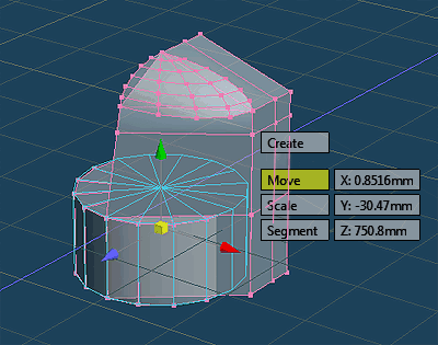 |
| Figure 7. I want to put a cylindrical shape to the top. |
This will also remove the part other, leaving a portion of the quarter that apply to the top reference shape.
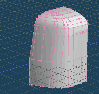
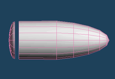
And so that you meet at the beginning reference shape by scaling adjusts the cylindrical so as to select the [Scale] As before, matching on each side. This will give you the chance to form, such as the following. (Figure 8)
 |
| Figure 8. Fitting at the top front shape change due to the expansion cylindrical |
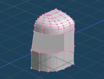
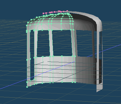
Finally, select the side portion relating to the roof of the cross-section of the sphere by focusing on the upper side of the top section again.
The tension in the Z-axis minus direction the side you have to select it and then select [Pull] , and then form a polygon roof portion.
You have put a polygon a portion between using the [Create] between the cylindrical portion and the front sphere the previous head further.
Nose shape railway vehicle will reveal here to be finished. You have to separate object from the top reference shape that made the first polygons spliced cylindrical and spherical cross-section and cross-section which I made earlier at this time.
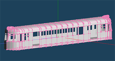
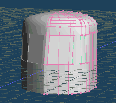
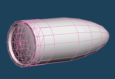
Select the [Separated | Mirroring] in Object Panel on top shape formed here. This will give you the chance to shape symmetrical shape the other half is automatically formatted. (Figure 9)
 |
| Figure 9. Top shape revived the left half mirroring |
(5) The elaboration head shape
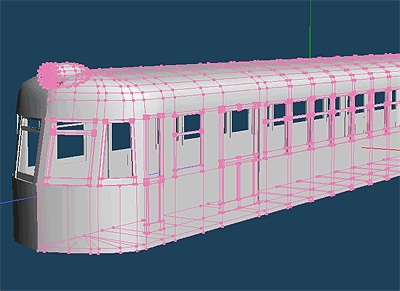
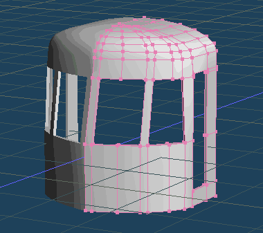
I'll open the window to the top shape from here.
Style of placing the four windows in the front round shape is a curved surface was popular in the 13's Showa in the "streamlined vehicle" was the trend. We will create shape from the beginning that you just created the window placement. The larger two windows in the center, work to be executed only designed smaller windows beside Given the balance front window to say that. It is OK to add and modify curved surfaces dividing line nose shape that was created at present, only by changing the placement window like it to be able to do so.
I will add the appropriate dividing line in the [Knife] a new dividing line in particular. Select together vertically coordinate point in the [Select] for them, and moved to the appropriate position in the [Move] to fit the dividing line these. As a result, the dividing line nose shape will change as shown in Figure (Figure 10)
 |
| Figure 10. Move dividing line that matches the window placement and the addition of the dividing line to the top shape. |
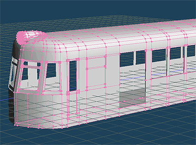
Place to be a window We are now finalized. I make door crew to get on and off while you're at it even if I put a dividing line. Select the polygon corresponding to the windows and doors these, and push the car direction (negative direction) the and select push the [Menu > Selected > Extrude faces] . (Figure 11)
 |
| Figure 11. To make a dent in the crew door and window in the [push the surface]. |
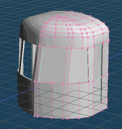
And to confirm the nose shape of it at once elaborated the inside of the body further. Select it in the [Select] the nose shape except for the polygon of the window around to do so, you can duplicate as a separate object top shape by selecting [Menu > Selected > Copy].
Flip the plane direction by selecting reversal of [Menu > Selected > Invert] a nose shape that you then duplicate. Top shape you have selected by Trends in the car side. Then multiply the reduction by the thickness of the wall at the center of the nose shape by selecting [Scale] and maintain the selection state. (Figure 12)
 |
| Figure 12. Formation on the inside of the nose shape |
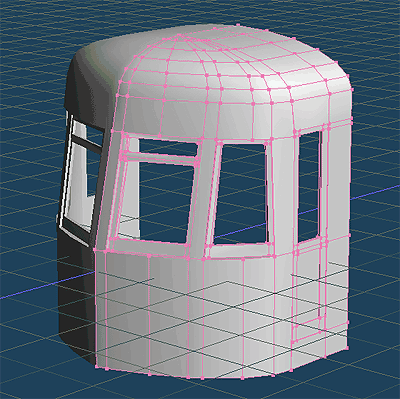
Thickness can now be set in the front and back of the head shape now. Crew door frame and window frame of the nose shape is formed and go hand in the [Create] a polygon that connects the front and back. (Figure 13)
 |
| Figure 13. Top shape window frame and set the crew door frame |
In addition, the front window frame of the driver's seat and I'll also performed formation preparation crew door here.
I am pasting the polygon one by one as a separate object in the window frame part for the first.
Window frame polygon that was removed was split originally two pieces, in order to create the actual window, consider to be created from a single polygon intentionally here. A result of the work up to this point, is shown in the following figure: The head shape. (Figure 14)
 |
| Figure 14. I set the temporary polygon crew door for creating windows and |
Turn on the dividing line the frame section by selecting [Knife] for polygons to set this, to isolate the window portion and window frame part. Remove the polygon (partial line-of-sight the inside) part to be the window when you are finished put. (Figure 15)
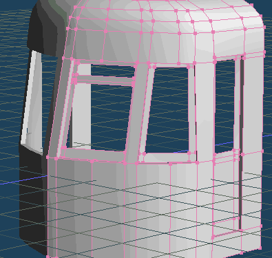 |
| Figure 15. Leave a window frame to put the dividing line in the window polygon |
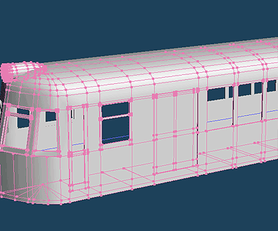
Window frame the remaining selected in the [Select], then select push the [Menu > Selected > Extrude faces], we will put the thickness extruding the window frame part. Window frame as shown in Figure is completed in the end. (Figure 16)
 |
| Figure 16. Window frame nose shape was completed with a thickness |
(6) Creating headlight
Appearance seems fairly railway vehicle window frame and the shape of the top part is made. There are, however, indispensable to the lead vehicle. It is a headlight that is headlight.
Creating a headlight in the same way as when nose shape, I will continue to promote a combination of basic shapes. The "Sphere" basic shape you want to use this time is the "ring".
You will be just a little bit to talk about the design of the headlight in front of the modeling.
At the time streamlined became popular first in Japan, no headlight is incorporated into the body still, I was put on the outside of the vehicle body with his installation base frame. But when it comes to the sleek but this would all the way under the influence of the wind. Where it is embedded in the body half a headlamp, it was established on top of the roof such cases embedded in the opposite direction like a cannonball. "This bullet-shaped headlight" I was indispensable thing streamlined design of the time.
We are going to make it by modifying the spherical shell this type is Sample image.
So by selecting the spherical from [Primitive], we will have on the roof nose shape the center point. I leave the ring at the same time creating shape that make up the headlamp cover part at this time.(Figure 17)
 |
| Figure 17. Placed basic shapes that make up the headlight (spherical + ring) |
I will split into two this sphere. Use as a lens of the headlamp is one, and in case bullet-shaped headlight rear the other. The deformed over the [Scale], respectively. (Figure 18)
 |
| Figure 18. Applying scale deformation, respectively, as divided by a central spherical |
When combined by adjusting the size of the ring which was set to the headlamp casing the end, the shape of the headlamp is completed. (Figure 19)
 |
| Figure 19. Completion of the headlamp |
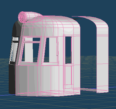
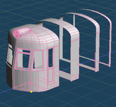
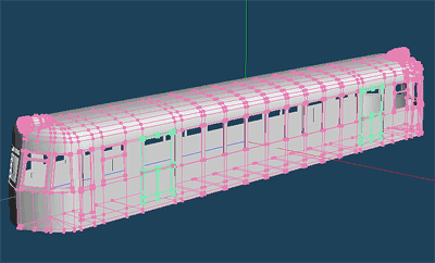
When placed at the head shape this, headlight is complete. (Figure 20)
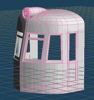 |
| Figure 20. Placement of the shape to the top of the headlamp |